|
|
|
|
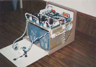
Click on image for larger picture TIC-5000 Aircraft / Helicopter Tachometer Indicator
Calibrator
The
TIC-5000 is a high precision aircraft/helicopter tachometer simulator
designed to calibrate three-phase tachometer indicators.
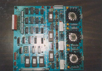
A high accuracy quartz master oscillator is used to drive digital circuitry which generates timing signals for the tester. Operator control settings in either the fixed or variable speed modes apply different divisors to the master oscillator signal to generate frequencies which are multiples of the desired output frequencies. The divided master oscillator signal is used to drive a counter which clocks through ROM tables containing the digital equivalents of the three sinusoidal signals appearing at the tester output. The digital words from the ROM tables are applied to digital to analog converters, producing a three-phase sinusoidal output. Low pass filtering is applied to these signals for further noise and distortion reduction. After filtering the signals are applied to the output power amplifiers and then to the tester output connectors. The amplitude of the three-phase output signal is variable over a range of 0 to 30 VRMS line to line using a single control. The phase relationships of the three outputs are fixed at 120 degrees.
The
output frequency changes immediately whenever the operator changes the
variable frequency setting or switches between fixed frequency outputs. The
frequency output (RPM) indicator likewise changes immediately in response to
operator control settings. The variable frequency adjustment is linear in
nature, that is, the frequency increment obtained by turning the control a
given amount is the same over the complete range. The frequency resolution is
1 RPM over a range of 10 RPM to 6000 RPM. Technical
Specifications
Range: a.
Fixed Speed Settings: Crystal
referenced speed in 12 fixed steps of 10 percent each between 420 and 5040 RPM
corresponding to standard aircraft tachometer graduations. b.
Variable Speed Settings: 10.0
RPM (2.4 percent) to 6000 RPM (120 percent) in one continuous adjustment with
1 RPM resolution over the complete range. One RPM is 0.02 percent of 5040 RPM. Accuracy
of Speed Setting: +/-
0.02 percent overall accuracy. Stability
and Speed Constancy: a.
Stability of Crystal Reference: +/-
30 parts per million better (0 deg -70 deg C). b.
Speed control: Full
scale +/- 0.02 percent and is unaffected by +/- 10 percent fluctuations in
line voltage. Response
Time: Instantaneous
automatic adjustment to preset speed. The response time of aircraft tachometer
does not affect calibrator's operation, i.e. Rapid change in true RPM, % RPM
on Digital Counter. Operational
Environment: The
tester can be used on both flight tests and ground tests. Dimensions: The
standard model tester is housed in a commercial instrument case with
approximate overall dimensions of 11" long x 11" wide x 10"
high. Weight: Approximately
14 pounds. Power
Requirements: 115
VAC from 50-440 Hz. Power
Output: 50
watts, 3 phase sinusoidal signal to a star connected load (minimum 20 ohms per
phase) 0-30 volts line to line. Interference: Complies
with MIL-STD-461A, Category IV. Interface: a.
Non-Illuminated MS 3106E-10SL-3 Female Tachometer Connector b.
Illuminated MS 24266R-14B7 SN Female Tachometer Connector c.
Aircraft Tach MS 3101E-14S-7P Female Tachometer Connector Display: A
digital counter is included to display the true tachometer indication being
generated by the tester. Standards: Complies
with all applicable NEMA and OSHA standards for good commercial practice. Options: An
optional RMS output voltage indicator is available.
|
|
|